Industrial FDM 3D Printing for Functional Parts
PartsMake produces durable prototypes and low-volume production parts with industrial-grade Fused Deposition Modeling. Balance structural integrity, material versatility, large-format capability, and cost efficiency in one reliable workflow.
900 mm
Maximum build dimension
±0.2%
Typical dimensional tolerance
1–5 days
Typical project lead time
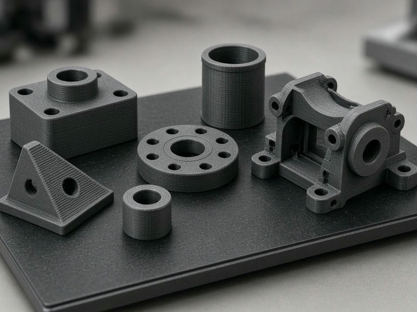
Built for engineering validation
High-performance thermoplastics, application-focused print settings, and secondary finishing for parts that need to work—not just look right.
FDM production capabilities
A dependable process for functional thermoplastic parts
Our process is optimized for mechanical reliability and dimensional accuracy. We control extrusion parameters, material selection, orientation, infill, and finishing around the intended performance of your part.
Translate requirements into print settings
We align nozzle size, layer height, shell thickness, infill, and polymer selection with load, temperature, fit, and finish requirements.
Produce parts for real-world testing
Industrial FDM supports functional prototypes, fixtures, housings, brackets, and low-volume components made from production-grade thermoplastics.
Finish critical interfaces
Sanding, vapor smoothing, CNC machining, tapping, and metal thread inserts help parts meet visual, assembly, and repeat-use requirements.
Scale large prototypes efficiently
A build volume up to 900 × 600 × 900 mm supports large parts and consolidated assemblies while reducing tooling investment and part count.
Technical data
Specifications designed around engineering decisions
Select a configuration that reflects the size, strength, speed, and surface requirements of your application. Final recommendations are confirmed during technical review.
Discuss your specification| Specification | Capability | Engineering relevance |
|---|---|---|
| Maximum build size | 900 × 600 × 900 mm | Large housings and consolidated assemblies |
| Typical layer height | 0.016–0.30 mm | Resolution or throughput trade-offs |
| Dimensional tolerance | ±0.2% min ±0.2 mm | Fit, assembly, and validation control |
| Nozzle diameters | 0.2–0.8 mm | Detail, bead strength, and print speed |
| Fill density | 0–100%, customizable | Weight, stiffness, and material usage |
Material portfolio
Engineering polymers for demanding use cases
From form-fit checks to high-temperature end-use components, we help match the polymer to the environment your part must withstand.
01 / Standard engineering
ABS, PLA, PETG
Practical materials for form-fit testing, general prototypes, visual models, and applications with moderate performance demands.
02 / High strength
Nylon PA6/PA12, PC
Durable options for functional testing, impact exposure, load-bearing components, jigs, fixtures, and housings.
03 / Advanced high temperature
PEI (ULTEM), PEEK
High-performance polymers for elevated-temperature, chemical-resistance, and demanding engineering environments.
Design for mechanical performance
Print direction, infill, and shell design determine strength
FDM parts are anisotropic: their strength varies by direction because layers are deposited sequentially. We review load paths and critical features before production so the printed structure supports the way the part will be used.
Orientation and layer adhesion
Tensile strength is typically highest along the X and Y axes. Critical load-bearing features are oriented parallel to the build plate where possible to reduce the risk of delamination under stress.
Infill for strength-to-weight
We tune infill pattern and density to the load requirement. Densities above 40% can substantially increase compressive strength, while gyroid and hexagonal patterns provide efficient structural support.
Shells and critical walls
For maximum durability, increasing perimeter or shell thickness is often more effective than simply increasing infill because outer walls contribute significantly to overall rigidity.
Large-format cost control
More size without unnecessary material or post-processing
Large FDM parts can replace multi-piece assemblies and avoid the tooling expense of injection molding. Our engineering team helps control cost from the first orientation decision through final finishing.
- Minimize support structures: orient complex geometry to reduce overhangs, waste, and support removal time.
- Hollow large parts: use internal cavities where appropriate to reduce material consumption without sacrificing functional integrity.
- Consolidate assemblies: print industrial housings and large-scale models as fewer parts to simplify testing and handling.
Project economics
900 × 600 × 900 mm
Build volume for large-scale prototypes and assemblies
Low tooling cost
A practical route for low-volume production and custom parts
1–5 working days
Typical lead time, subject to geometry and material review
Finish and application fit
From visible layer lines to production-ready interfaces
FDM naturally creates visible layer lines. We offer secondary processes when surface appearance, sealing, assembly, or precision interfaces require additional treatment.
Sanding and polishing
Reduce surface roughness for visual models, aerodynamic testing, and presentation parts.
Vapor smoothing
Improve compatible thermoplastics with a sealed, semi-gloss exterior that is easier to clean and visually uniform.
CNC secondary machining
Refine press-fit bearings, mating surfaces, and other interfaces that need tighter tolerances than standard FDM alone.
Tapping and thread inserts
Add durable, repeatable connection points for assemblies that will be opened, serviced, or reused.
Project suitability
When FDM is the right production route
Functional testing
Snap-fits, jigs, and fixtures that require the mechanical properties of ABS or Nylon.
Low-volume production
End-use brackets and housings where injection-molding tooling would be disproportionate to the required volume.
Large-scale models
Concept models and industrial housings that exceed the build limits of many resin-based technologies.
Common engineering review points
- •Intended application and service environment
- •Required material, strength, and temperature resistance
- •Load direction, critical dimensions, and mating interfaces
- •Surface finish, support strategy, and post-processing needs
Frequently asked questions
Practical answers for your FDM project
Request a quote
Send your CAD files for an FDM technical evaluation
PartsMake provides rapid lead times—typically 1 to 5 working days—for FDM projects. Upload your files and tell us how the part will be used so we can recommend the optimal material, orientation, infill, and finishing route.
Email:
Facility location:
Project details
Include your application, material requirements, quantity, and any critical performance targets.