Polycarbonate CNC Machining
Precision CNC Machining for Polycarbonate Components
Build high-impact, transparent, heat-resistant PC components with a machining process engineered for dimensional control, optical quality, and long-term reliability.
±0.01–0.05 mm
Standard machining tolerance
88–90%
Typical optical transmittance
24–48 hrs
Standard quote response
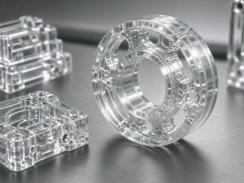
Material focus
High impact resistance. Optical clarity. Thermal stability.
Engineering data
Polycarbonate properties that guide part design
Polycarbonate balances toughness and transparency, but its physical characteristics require careful tooling, thermal control, and finishing decisions during machining.
Design note
Machined wall thickness can reach 0.5 mm depending on geometry, support, and the required cosmetic or optical specification.
| Property | Typical value | Design relevance |
|---|---|---|
| Optical transmittance | 88%–90% | Supports transparent covers and optical features |
| Impact strength, notched Izod | 600–850 J/m | High resistance to shock and impact |
| Heat deflection temperature | 130°C–140°C at 1.8 MPa | Useful for elevated-temperature applications |
| Density | 1.20 g/cm³ | Supports lightweight component design |
| Mold shrinkage | 0.5%–0.7% | Important when transitioning to molding |
| Minimum machined wall | 0.5 mm | Depends on geometry and process support |
Process control
A machining process tuned for PC
Polycarbonate is sensitive to heat buildup. Uncontrolled cutting can cause melting, discoloration, gumming, or internal stress, so each operation is managed around stable temperatures and clean chip evacuation.
Sharp tooling
High-rake, polished carbide end mills minimize shear forces and reduce the risk of material gumming.
Thermal management
Controlled coolant application helps maintain dimensional stability and limit thermal expansion during milling.
Chip evacuation
High-pressure air blasts and optimized flute geometry prevent re-cutting and surface degradation.
Tolerance control
Standard tolerances range from ±0.01–0.05 mm, with precision features down to ±0.005 mm depending on geometry.
Surface engineering
From machined finish to optical clarity
Transparent PC parts often need more than dimensional accuracy. We offer finishing routes that help remove tool marks, restore transparency, and achieve a glass-like appearance where the application demands it.
Machined finish
Suitable for internal components and functional parts where cosmetic clarity is not the primary requirement.
Hand polishing
Multi-stage sanding and buffing removes tool marks and helps restore transparency.
Vapor polishing
A specialized solvent-vapor process allows the outer layer to re-flow, eliminating micro-scratches and producing near-perfect optical clarity.
Reliability safeguard
Manage internal stress before it becomes a field failure
Polycarbonate can be vulnerable to environmental stress cracking when residual machining stress combines with incompatible chemicals.
- ✓ Stress-relief annealing: Controlled thermal annealing for complex geometries and thin walls helps reduce residual stress.
- ✓ Tool path optimization: Trochoidal and high-speed paths distribute cutting forces and reduce localized stress concentrations.
- ✓ Chemical compatibility: Coolants and cleaning agents are reviewed to protect PC integrity.
Production strategy
CNC machining or injection molding?
The right process depends on your project stage, geometry, and production volume. Compare the routes before committing to tooling.
Best for
Prototypes and bridge production
Advantages
Complex internal geometries, fast design iterations, and no high upfront steel tooling cost.
Typical path
Machine initial prototypes, validate the design, then evaluate molding as demand increases.
Best for
High-volume production
Volume guide
Usually recommended at 1,000 or more units when reducing unit cost justifies the tooling investment.
Planning note
Account for approximately 0.5%–0.7% mold shrinkage and validate surface requirements before production tooling.
Quality assurance
Inspection built around transparent, thin-wall, and cosmetic features
Every Polycarbonate component follows an inspection protocol aligned to the engineering drawing and the functional or cosmetic requirements of the application.
CMM inspection
Complex 3D profiles and positional tolerances.
Optical measurement
Thin-walled or transparent features measured without surface damage.
Surface roughness testing
Verification of cosmetic and optical surface requirements.
Full documentation
FAI reports, material certifications, and batch traceability.
Common PC engineering questions
How do you reduce stress cracking? +
We combine optimized tool paths, controlled thermal conditions, stress-relief annealing where appropriate, and a review of coolant and cleaning-agent compatibility.
Can CNC-machined PC be optically clear? +
Yes. Machined, hand-polished, and vapor-polished routes are available. The best option depends on the required clarity, geometry, and surface specification.
Which CAD formats can I submit? +
Submit STEP, IGS, or Parasolid files together with technical drawings and any required surface or inspection specifications.
Project consultation and RFQ
Turn your PC design into a manufacturable part
Whether you need one high-precision prototype or a repeat production run, our engineering team can review your Polycarbonate specifications and recommend a cost-effective production path.
Email:
Address:
Lead time: Standard quotes provided within 24–48 hours.
Request a Polycarbonate quote
Send your CAD files and technical drawings for a formal quotation.