Integrated CNC Turning & Milling
Precision Mill-Turn Machining Services
PartsMake produces high-precision cylindrical components with turning and milling features completed in a single setup. Reduce secondary operations, shorten lead times, and protect critical geometric relationships for demanding industrial parts.
±0.005 mm
Tolerance capability
0.001°
C-axis resolution
1–100,000+
Production quantities
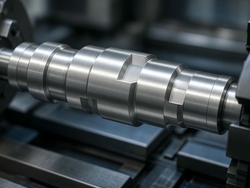
One setup. One datum reference.
Turn, mill, inspect, and release complex parts with fewer transfers.
The manufacturing challenge
Complex milling features on turned parts, without repeated repositioning
Off-center holes, keyways, slots, and complex profiles often force a part to move between a CNC lathe and a machining center. Each transfer adds handling time and introduces the possibility of cumulative errors from re-fixturing.
Fewer process transfers
Turning and milling are integrated on one multi-axis platform, reducing movement between machines and workholding systems.
Stable geometric relationships
A shared datum reference helps preserve concentricity and the relationship between turned diameters and radial milling features.
More predictable project flow
Fewer secondary operations can reduce cycle time and simplify planning from prototype production through scalable volume manufacturing.
Process comparison
Choose the workflow that protects your part geometry
Mill-turn machining combines the power of a CNC lathe with the versatility of a machining center. The part remains held in the main spindle while cylindrical and off-center features are produced.
Single setup workflow
Load raw material → turn and mill → finished part
01
Establish one primary datum in the main spindle.
02
Complete turning and driven-tool milling features.
03
Inspect a finished component with reduced handling.
Benefit: Single datum reference, superior concentricity, and reduced cycle times.
Multi-stage workflow
Turn on lathe → transfer to milling machine → re-clamp → inspect
01
Turn the cylindrical form on a CNC lathe.
02
Move, fixture, and re-reference the part for milling.
03
Mill features and complete final inspection.
Risk: Increased tolerance stack-up and handling time due to repeated clamping and fixture changes.
Machine capability
Mill-turn technical specifications
Advanced multi-axis equipment supports challenging geometries with high repeatability. Confirm project-specific workholding and bar capacity during RFQ review.
Max turning diameter
Ø500 mm
Max bar diameter
Confirm per machine setup
Chuck size
Confirm per part envelope
Max turning length
1000 mm
Y-axis travel
Included for off-center milling
Live tooling
High-torque driven tools
C-axis indexing
0.001° resolution
Tolerance
Down to ±0.005 mm
Surface roughness
Ra 0.4–3.2 μm
Best suited for
Turned parts with integrated milling features
Part fit
Ideal applications for mill-turn machining
This process is engineered for components that demand precision, cylindrical geometry, and complex feature integration.
Aerospace & Defense
Actuator housings, valve bodies, and structural shafts.
Medical Devices
Surgical instruments and implant components requiring high surface finish.
Automation
Complex drive shafts, multi-face connectors, and precision bushings with radial milling features.
Oil & Gas
High-pressure fittings and specialty connectors with custom threading.
Material expertise
Machining support across demanding material families
Stainless steels
303, 304, 316L, 17-4PH, 15-5PH
Alloy & tool steels
4140, 4340, D2, H13
Non-ferrous materials
Aluminum 6061 and 7075, titanium Grade 2 and 5, brass, and copper
Engineering plastics
PEEK, PTFE, POM, and Nylon
Single-setup quality control
Keep inspection aligned with the manufacturing datum
Every mill-turn project follows a quality protocol designed to verify compliance with engineering drawings while maintaining material and batch traceability.
Dimensional accuracy
CMM and optical measurement systems verify critical dimensions and features.
Traceability
Material certification and batch tracking are maintained from raw material to shipping.
Documentation
FAI reports and full dimensional reports are available upon request.
From prototype to production
A manufacturing range built around your program
Prototype production
Single-piece engineering samples
Validate form, fit, and process direction before scaling.
Production volume
1 to 100,000+ pieces
Scale output to match your program requirements.
Secondary operations
Ready-to-assemble components
In-house grinding, EDM, and surface finishing support a complete part solution.
Request a quote
Send your mill-turn project to our engineering team
Submit your CAD files and technical requirements for a formal review of part geometry, lead time, and cost.
Accepted CAD formats: STEP, IGES, or DXF
Email your RFQ:
Facility location: