Sheet Metal Design Guide
Optimize your parts for manufacturing with practical guidance on bend radius, K-factor, hole clearances, relief design, and flat-pattern accuracy.
PartsMake transforms CAD designs into precision metal and plastic components, helping procurement teams and engineers identify design risks before production begins.
0.44
Typical K-factor for standard steel and aluminum alloys
1.5×T
Minimum hole-to-bend thickness component before radius
Design fundamentals
Build geometry around the forming process
Successful sheet metal fabrication starts with geometry that accounts for material deformation. These core principles help protect part integrity, simplify production, and control cost.
Bend radius and K-factor
The internal bend radius should ideally match the material thickness (T). A smaller radius can create stress fractures in the bend zone.
The K-factor represents the neutral-axis position relative to material thickness and is essential for calculating accurate flat patterns. We typically use 0.44 for standard steel and aluminum alloys.
Hole-to-bend clearance
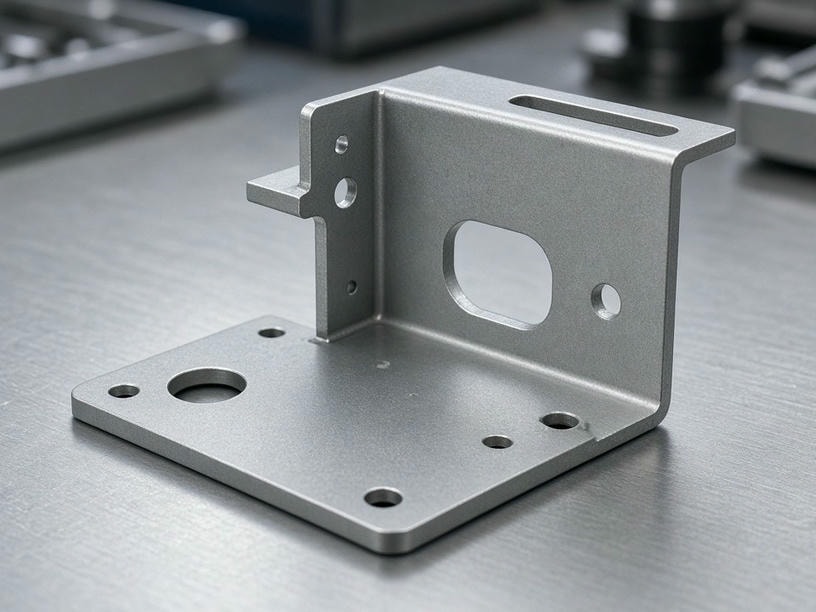
Keep holes away from the bend line to prevent distortion and tearing during forming.
Recommended minimum: 1.5 × material thickness + bend radius, measured from the hole center to the bend start.
Hole-to-edge and relief
Place holes at least 2 × material thickness from any part edge. Near-edge bends also need relief cuts to prevent tearing or material pull.
Relief width should be at least the material thickness, with a depth greater than the bend radius.
Reference data
Standard design parameters
Use these starting points to standardize sheet metal components. If your design falls outside these ranges, submit the CAD files for a feasibility review before material is committed.
Fast rule set
- →Target an internal bend radius near material thickness.
- →Keep holes at least 2 × T from free edges.
- →Add relief when a bend approaches a side edge.
| Material thickness (mm) | Min. bend radius (mm) | Min. hole-to-edge (mm) |
|---|---|---|
| 0.5 – 1.0 | 0.5 | 1.5 |
| 1.5 – 2.0 | 1.5 | 3.0 |
| 2.5 – 3.0 | 2.5 | 4.5 |
| 3.0 – 5.0 | 5.0 | 7.5 |
These values are design guidelines. Actual feasibility depends on alloy, tooling, bend sequence, tolerances, and part geometry.
Design review before production
Catch costly sheet metal errors early
Small geometry decisions can create secondary operations, poor fit, distortion, or production delays. Submit your STEP and DXF files early so our engineers can provide clear, actionable feedback.
Hole too close to a bend
A hole placed inside the forming zone may elongate or deform. Move it beyond the recommended hole-to-bend distance or evaluate a revised bend sequence.
Bend radius smaller than material thickness
An aggressive inside radius can cause cracking, especially in less ductile alloys. Increase the radius or confirm the material and tooling combination during review.
No relief at a near-edge bend
Without a relief notch, the bend can pull or tear the side edge. Add a relief with suitable width and depth before release to manufacturing.
What we check
A practical engineering review of every CAD file
- 01Tolerance stack-ups: We check whether mating parts will fit as intended.
- 02Manufacturing feasibility: We identify features that are impossible or cost-prohibitive to produce.
- 03Material selection: We validate alloy suitability for the intended environment and use case.
- 04Flat-pattern logic: We review bend allowances, K-factor assumptions, relief, and finished dimensions.
End-to-end production support
From prototype to production-ready assembly
PartsMake bridges the gap between engineering intent and physical reality, coordinating processes and quality requirements throughout your production lifecycle.
CNC machining
3-, 4-, and 5-axis milling for structural components and housings.
Precision turning
Swiss and multi-axis turning for shafts, pins, and bushings.
Sheet metal fabrication
Laser cutting, CNC bending, welding, and hardware insertion.
Injection molding
Production-grade tooling for plastic housings and functional parts.
Additive manufacturing
SLA, SLS, and metal 3D printing for rapid iteration.
Secondary finishing
Anodizing, powder coating, bead blasting, and plating.
Built for demanding applications
Support across your production lifecycle
Whether you need one prototype, a pilot run, or full-scale production batches, our project management team supports consistency at every stage.
Common review questions
Why does K-factor matter?+
It locates the neutral axis during bending and helps determine the developed flat length, reducing dimensional errors in the finished part.
What files should I submit?+
Send STEP and DXF files whenever possible, along with material, finish, tolerance, and annual volume requirements.
Can designs outside the table still be made?+
Potentially. Alloy, tooling, bend sequence, and feature geometry all affect feasibility, so an engineering review is the best next step.
Request a manufacturing quote
Turn your design into a manufacturable part
Send your technical drawings and 3D files for a comprehensive DFM review and quote. Include material specifications, surface finishing requirements, and annual volume estimates.
Engineering inquiry
Share your requirements with the PartsMake team.
PartsMake