Multi-material injection molding
Precision Overmolding Services
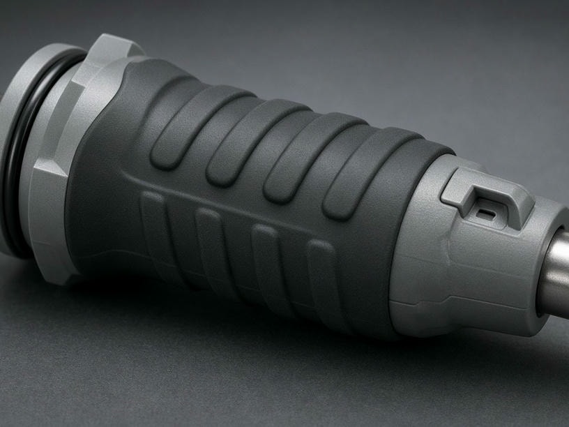
Create functional, ergonomic, and durable parts by combining rigid substrates with TPE or TPU elastomers. PartsMake manages material compatibility, bonding, tooling, cavity pressure, and production quality from DFM through mass production.
50–800
Ton injection machines
20A–90A
Shore A hardness range
±0.05 mm
Minimum stated tolerance
Process focus
Bonding and insert stability
Production support
Manual or automated placement
Technical capabilities
A controlled process for multi-material parts
Our overmolding workflow is designed for products that need a reliable interface between a rigid substrate and a flexible or soft-touch surface.
| Parameter | Specification |
|---|---|
| Material combinations | Rigid ABS, PC, Nylon, and similar substrates with TPE or TPU |
| Shore A hardness | 20A to 90A |
| Typical overmold thickness | 0.5 mm to 3.0 mm |
| Bonding types | Chemical adhesion and mechanical interlocking |
| Dimensional tolerance | ±0.05 mm to ±0.10 mm |
| Surface finish | SPI A1–D3, VDI, and custom textures |
| Color selection | Custom elastomer color selection and appearance matching |
| Mold life | 10,000 to 1,000,000+ cycles |
Material engineering
Substrate plus overmold compatibility
A dependable overmold starts with the right material pair. We evaluate thermal behavior, chemical compatibility, surface geometry, and end-use requirements before tooling.
Two bonding strategies
Chemical adhesion allows compatible molecular structures to fuse at the interface. Mechanical interlocking uses undercuts, holes, ribs, or textured substrate surfaces when chemical bonding is insufficient.
Material compatibility reference
A starting point for DFM and material selection
| Substrate | Recommended overmold | Bonding method |
|---|---|---|
| ABS | TPU / TPE | Chemical |
| PC | TPU / TPE | Chemical |
| Nylon (PA) | Nylon-grade TPE | Chemical |
| PP | PP-grade TPE | Chemical |
| POM | TPE | Mechanical interlock only |
Design for manufacturing
Design decisions that protect quality
Overmolded components require coordinated substrate geometry, flow behavior, and ejection design. Our engineering review focuses on the details that influence adhesion and repeatability.
Wall thickness
Keep the overmold consistent. Excessive thickness can create sink marks and cooling issues, while walls below 0.5 mm may cause short shots.
Gate location
Strategic gates help the elastomer flow across the substrate without displacement or weak knit lines.
Draft angles
A minimum 1°–2° draft on overmolded features supports ejection and helps prevent surface marring.
Structural ribs
Place ribs and bosses in the substrate for structural integrity rather than relying on the soft overmold.
TPE and TPU selection
Choose the soft material around the product need
TPE and TPU selection should reflect the required feel, flexibility, wear behavior, bonding chemistry, and environmental exposure. We help align the elastomer with the substrate and the application.
TPE for soft-touch and grip
A practical choice for ergonomic handles, seals, gaskets, buttons, and anti-slip surfaces where a broad Shore A range and tactile finish are important.
TPU for demanding durability
Consider TPU where abrasion resistance, toughness, and resilient protective features are central to the component design.
Application fit
Built for soft-hard component integration
- 01Handheld toolsNon-slip grips for power tools and medical instruments.
- 02Seals and gasketsDirect overmolding onto rigid housings for weather-tight or dust-proof enclosures.
- 03Electronic housingsSoft-touch buttons and shock-absorbing bumpers for consumer electronics.
- 04Automotive componentsVibration-dampened clips and interior trim pieces.
Two-shot quality control
Risk management begins in the mold design
Two-shot and insert overmolding introduce risks that can affect adhesion, appearance, dimensional accuracy, and tool performance. We address these conditions before production.
Substrate displacement
Precision locating pins and custom mold nesting stabilize the substrate against injection pressure.
Flash at the interface
High-precision CNC machining supports tight shut-offs around the substrate surface.
Thermal degradation
Melt temperatures and cycle times are optimized to protect the structural integrity of the base part.
Project workflow
From CAD review to repeatable production
01
DFM review
Evaluate CAD models for wall thickness, draft, and bonding feasibility.
02
Mold design
Develop mold layouts, cooling channels, locating features, and shut-offs.
03
Tooling
Machine prototype or production-grade molds using CNC and EDM.
04
T1 sampling
Verify adhesion strength, appearance, and dimensional accuracy.
05
Production
Scale manufacturing with stringent quality control and secondary finishing.
Technical questions
Common overmolding considerations
When is mechanical interlocking required?+
Mechanical interlocking is used when chemical bonding is insufficient or when the material pair is inherently incompatible. Undercuts, holes, and textured substrate surfaces can lock the overmold in place.
What thickness range is typical for an overmold?+
The typical overmold thickness is 0.5 mm to 3.0 mm. The correct value depends on the required feel, flow path, geometry, hardness, and application performance.
Can insert placement be automated?+
Yes. The facility supports both manual insert placement and automated processes for high-volume production.
Start your project
Validate your overmolded part with an engineering review
Submit your STEP or IGES files to discuss material selection, adhesion strategy, tooling, and production requirements. Our engineering team will provide feedback to help optimize the design.
Recommended project information
- Substrate and preferred overmold material
- Target Shore A hardness and overmold thickness
- Required color, finish, tolerance, and annual volume
- STEP or IGES CAD files for DFM review
Request a quote
Share your requirements with the PartsMake engineering team.