Nylon injection molding expertise
Precision Injection Molding for Nylon and Reinforced Polymers
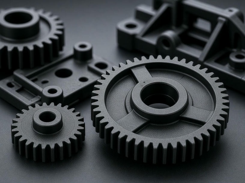
PartsMake processes PA6, PA66, and glass-filled nylon for demanding automotive, electrical, and structural applications. Our process controls address moisture, thermal stability, fiber orientation, and dimensional performance from mold design through production.
50–800 t
Clamping force range
±0.03 mm
Precision molding capability
Material control
Reliable nylon processing starts with moisture management
Nylon is hygroscopic and absorbs moisture from the atmosphere. If material is processed above the required moisture level, hydrolysis can reduce mechanical properties and create surface defects such as silver streaks.
Moisture target
Moisture content is maintained below 0.2% before processing.
Desiccant drying
Typical drying uses 80–100°C for 4–6 hours with desiccant dryers.
Thermal control
Melt temperatures are controlled to prevent thermal degradation, including 240–280°C for PA66.
Material window
Typical processing parameters for nylon
Final settings are confirmed against the selected grade, reinforcement level, geometry, and appearance requirements. The ranges below provide an engineering starting point for PA6, PA66, and reinforced nylon.
| Parameter | PA6 | PA66 | PA6 / PA66 + GF |
|---|---|---|---|
| Pre-process moisture | < 0.2% | < 0.2% | < 0.2% |
| Melt temperature | 230–260°C | 260–290°C | 270–300°C |
| Mold temperature | 40–80°C | 60–100°C | 80–120°C |
| Shrinkage | 0.8–1.5% | 1.0–2.0% | 0.3–0.8% |
| Glass fiber content | N/A | N/A | 15–50% |
| Recommended wall thickness | 1.0–3.0 mm | 1.0–3.0 mm | 1.0–3.0 mm |
Glass-filled nylon
Strength gains require control of fiber direction
Glass-filled nylon delivers the stiffness required for structural components, but glass fibers align with the flow direction. This creates anisotropic shrinkage and can lead to differential deformation or warpage.
Warpage prevention
Gate location, flow balance, wall thickness, and mold design are optimized to manage fiber-induced dimensional variation.
Surface appearance
High mold temperatures of 80–120°C and optimized injection speeds help create resin-rich surfaces and minimize the floating-fiber effect.
Design considerations for reinforced parts
- ●Review fiber flow direction against primary load paths and critical dimensions.
- ●Balance wall thickness to reduce uneven cooling and differential shrinkage.
- ●Use appropriate mold temperatures and injection speeds to reduce visible fiber exposure.
- ●Confirm cosmetic requirements early when a visible surface must remain fiber-free.
Production capabilities
From prototype molds to high-volume production
PartsMake supports the full product lifecycle with equipment and mold construction suited to high-wear glass-filled materials.
Mold bases
LKM, DME, and equivalent
Machine range
50–800 ton clamping force
Standard precision
±0.05–0.20 mm
Precision molding
Down to ±0.03 mm
01
Integrated finishing
- Insert molding: Brass or stainless steel threaded inserts for stronger fastening.
- Overmolding: Rigid nylon substrates combined with TPU or TPE soft-touch surfaces.
- Finishing: SPI/VDI texturing, laser marking, and painting.
02
DFM and mold design
- Draft angles: 0.5°–2° for reliable ejection of semi-crystalline materials.
- Ribs and bosses: Thickness is optimized to help prevent sink marks.
- Undercuts: Lifters and slides support complex geometries.
03
Quality assurance
- T1 sampling: Validate mold performance and material behavior.
- Dimensional inspection: CMM and precision gauges verify tolerances.
- Cosmetic inspection: Check fiber orientation, flash, and knit-line integrity.
Technical questions
Nylon molding considerations
Start your project
Bring your nylon component to production
Send your CAD files and technical requirements to PartsMake for a comprehensive DFM review and project quote. Our engineering team can evaluate material selection, drying requirements, glass fiber direction, wall thickness, and molding risks.
Project inquiry
Email:
Facility address: