DMLS / SLM Metal Additive Manufacturing
Metal 3D Printing for Complex, High-Performance Metal Parts
Produce prototypes, functional test parts, and low-volume production components that are difficult, expensive, or impossible to manufacture with conventional machining, casting, or fabrication.
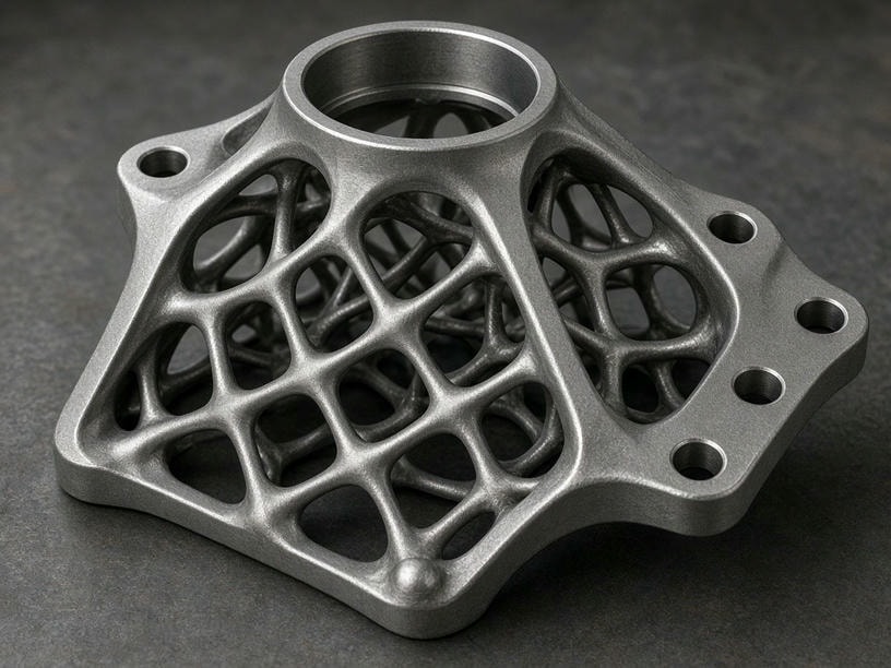
Our service supports internal flow channels, lattice structures, topology-optimized designs, lightweight parts, and consolidated assemblies in aluminum, stainless steel, titanium, and Inconel.
4
Metal families
99%+
Typical relative density
±0.2%
General planning tolerance
1–5
Typical additive days
Engineering review before production
Material, orientation, support strategy, thermal behavior, post-processing, and inspection requirements are assessed together.
Built for demanding applications
Metal additive manufacturing when conventional methods reach their limits
Metal 3D Printing is appropriate when part performance, geometry, lead time, or material efficiency is more important than conventional production economics.
Discuss your application →Complex geometry
Internal channels, lattice structures, manifolds, and forms that cutting tools or molds cannot reach.
Lightweight performance
Topology-optimized brackets, housings, supports, and structural components with reduced mass.
Fewer components
Consolidate assemblies to reduce fasteners, welds, alignment errors, inventory, and potential leakage paths.
Flexible production
Support prototypes, functional testing, replacement parts, custom tooling, and bridge production before tooling investment.
Technical capability
DMLS / SLM metal 3D printing capabilities
DMLS and SLM build parts layer by layer from metal powder, enabling features restricted by cutting-tool access, mold removal, or traditional assembly methods.
| Capability | Service range or planning reference |
|---|---|
| Metal processes | DMLS / SLM metal additive manufacturing |
| Available metal families | Aluminum, stainless steel, titanium, and Inconel |
| Typical layer height | 0.016–0.30 mm across additive technologies; metal settings depend on alloy, geometry, and detail requirements |
| Minimum feature size | Approximately 0.3–0.5 mm as a general reference; metal features require project-specific review |
| Dimensional tolerance | Approximately ±0.2% with a minimum of ±0.2 mm; dependent on geometry, orientation, alloy, and post-processing |
| Metal part size | Confirmed against the selected machine build envelope and submitted CAD model |
| As-built surface roughness | Typically approximately Ra 8–20 μm; actual results vary by orientation, powder, and feature location |
| Typical relative density | Commonly greater than 99% for suitable alloy and process conditions |
| Production quantity | 1–10,000+ pieces depending on size, material, finishing, and schedule |
| Typical additive lead time | Approximately 1–5 working days for suitable projects; post-processing may extend the schedule |
These values support early design and sourcing decisions. Final process windows, tolerance, surface finish, orientation, and post-processing requirements are confirmed during quotation.
Material selection
Choose the alloy around the application
Selection depends on operating temperature, mechanical loading, corrosion exposure, weight, fatigue requirements, and the required post-processing route.
Aluminum alloys
~2.70 g/cm³Lightweight housings, brackets, manifolds, heat-transfer components, and aerospace or automotive prototypes. Critical bores and interfaces may require CNC finishing.
Stainless steel
~7.9–8.0 g/cm³Functional prototypes, tooling, brackets, fluid components, and corrosion-resistant parts. Surfaces may require blasting, polishing, or machining.
Titanium alloys
~4.43 g/cm³Lightweight structural components, medical and aerospace prototypes, and high-strength parts. Support design, heat treatment, and machining access need careful planning.
Inconel alloys
~8.4–8.5 g/cm³High-temperature components for aerospace, energy, thermal systems, and demanding industrial applications. Thermal control and post-processing are especially important.
Density values are nominal references for common alloy families rather than guaranteed values for every grade. The specific alloy, process parameters, heat-treatment condition, and documentation requirements are confirmed before production.
Design for additive manufacturing
Design the part around what additive can unlock
The strongest benefits appear when a part is designed around additive manufacturing rather than simply converted from a machined design.
Engineering review focus
- • Minimum channel diameter and powder evacuation
- • Build orientation and thermal distortion risk
- • Support removal access and critical surfaces
- • Machining datums, stock, and inspection points
Internal channels and conformal passages
Evaluate conformal cooling channels, heat exchangers, lightweight fluid manifolds, vacuum and pneumatic components, and internal routing around mounting features. Blind or enclosed cavities may require dedicated powder evacuation features.
Topology optimization and lightweight structures
Remove material from low-load regions while preserving load paths, mounting interfaces, and stiffness requirements. Organic brackets, ribbed frames, lattice-filled sections, and generative design concepts can be reviewed for manufacturability.
Part consolidation
Combine multiple conventional parts into one component to reduce fasteners, joints, welded interfaces, assembly time, leakage paths, inventory complexity, and alignment errors.
Supports, overhangs, and orientation
Orientation affects dimensional accuracy, surface roughness, residual stress, support volume, build time, and functional surface quality. Support structures are removed after printing, so difficult-to-access areas should be identified before production.
Beyond the build
Post-processing for finished metal parts
The printed condition is one stage of production. We define finishing around the required function, appearance, and dimensional control.
Support removal
Prepare the part for subsequent finishing while balancing stability, accessibility, and material use.
Heat treatment
Relieve residual stress and achieve the required material condition based on alloy and geometry.
HIP processing
Consider hot isostatic pressing for improved internal consistency and reduced residual porosity.
Blasting and polishing
Create a more uniform matte appearance or improve selected cosmetic surfaces where access permits.
CNC secondary machining
Precision machining is recommended for bearing seats, sealing faces, mounting planes, bores, reamed holes, datum surfaces, threaded holes, flat interfaces, and critical mating features.
Threads and inserts
Printed threads are not appropriate for every load or service condition. Tapped holes and thread inserts can be evaluated for durable connections and repeated assembly.
Quality planning
Surface finish and dimensional control designed into the quote
Metal 3D Printing produces a textured as-built surface that varies by orientation and feature location. Downward-facing surfaces, support-contact areas, internal channels, and curved features may require different finishing strategies.
We can help define
• Critical dimensions
• Functional tolerances
• Machined datum features
• Thread requirements
• Sealing surfaces
• Surface roughness
• Support contact locations
• Inspection points
±0.2%
General dimensional capability, with a minimum of ±0.2 mm, subject to geometry and process conditions.
A practical production route
From CAD file to finished metal part
Every project follows a review-led process so that material, build strategy, finishing, and inspection are aligned before production.
- 1
File and requirement review
Review the CAD model, drawing, quantity, material, operating conditions, and critical features.
- 2
Manufacturability assessment
Evaluate wall thickness, channels, overhangs, support access, powder removal, orientation, and distortion.
- 3
Material and process selection
Recommend an alloy family and DMLS / SLM approach based on performance and production requirements.
- 4
Build planning and printing
Select orientation, support strategy, nesting approach, finishing datums, and produce the approved component.
- 5
Post-processing and final review
Complete specified support removal, heat treatment, HIP, machining, finishing, tapping, inserts, and final checks.
Process selection
When metal 3D printing is the right process
- ✓Internal geometry cannot be drilled or milled.
- ✓Weight reduction has measurable value.
- ✓Production volume is limited or a design is still changing.
- ✓Multiple components can be consolidated.
- ✓Conventional machining would create substantial material waste.
A balanced manufacturing recommendation
Conventional CNC machining may be more economical for simple prismatic parts, large material-removal jobs, or high-volume components with stable designs. Casting or forming may be preferable when production volumes justify tooling.
We review the geometry and recommend a practical route rather than forcing every design into additive manufacturing.
Ask for a process reviewRFQ preparation
What we need for a Metal 3D Printing quote
Send as much of the following information as available. If the design is not finalized, we can begin with the CAD model and intended application.
Start your engineering review
Request a Metal 3D Printing quote
Send your design to PartsMake for a practical review of material, build orientation, supports, tolerances, finishing, and production quantity.
Contact PartsMake
Include your CAD file, drawing, target alloy, quantity, and delivery requirements in your inquiry.
Email:
Address: