Press Brake Bending Services
Precision Sheet Metal Bending for Production-Ready Parts
PartsMake provides contract sheet metal bending and forming for enclosures, chassis, brackets, and structural components. From initial prototypes through high-volume production, our high-tonnage press brakes deliver dimensional consistency and structural integrity.
200 t
Maximum press force
3000 mm
Maximum bend length
±0.5°
Bend angle tolerance
50,000+
Production-run support
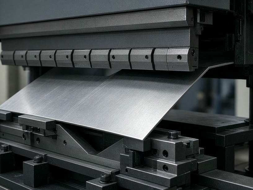
Engineering-led forming
CAD review, bend sequence planning, springback compensation, and inspection are coordinated before production begins.
The mechanics of deformation
Accurate bending starts with material behavior
When sheet metal is formed, the inside of the bend compresses while the outside stretches. Between these zones is the neutral axis, where the material neither stretches nor compresses.
Our engineering review uses this behavior to establish flat patterns, tooling choices, bend deductions, and compensation values before cutting and forming.
Bend allowance
The arc length of the neutral axis between the tangent points of the bend.
K-factor
The ratio of neutral-axis location to material thickness, used to calculate the correct flat pattern.
Springback
We compensate for the material’s return toward its original shape after pressure is released.
Press brake capabilities
Capacity matched to your geometry and material
We review every CAD file to optimize the bend sequence for material thickness, tooling availability, and finished-part access.
| Specification | PartsMake Capability |
|---|---|
| Press brake tonnage | Up to 200 tons |
| Maximum bending length | 3000 mm |
| Length accuracy | Typical bending tolerance of ±0.25 mm |
| Angle accuracy | ±0.5° |
| Minimum material thickness | 0.3 mm |
| Maximum material thickness | 20–25 mm, depending on material |
| Material range | Aluminum 5052 and 6061, stainless steel 304 and 316L, mild steel, galvanized steel, copper, and brass |
Engineering module
Flat pattern calculation logic
We derive the flat pattern from your 3D CAD model instead of simply bending a cut blank. The engineering team verifies bend allowance and K-factor assumptions before laser cutting.
Bend deduction
The difference between the sum of flange lengths and the flat pattern length. Correct bend deduction ensures the finished part meets final assembly dimensions.
Calculation sequence
- 1
Review the 3D model
Identify bend angles, inside radii, flange dimensions, and assembly datums.
- 2
Set material variables
Apply thickness, K-factor, grain direction, temper, and springback behavior.
- 3
Verify the flat blank
Confirm bend allowance and bend deduction before the cutting stage.
Design for manufacturability
Avoid common bending design errors
Small details in the flat pattern can affect cracking, hole position, part fit, and production cost. These checks are part of our engineering review.
Hole-to-bend distance
Holes too close to the bend line can deform. As a general rule, keep the hole edge at least 1.5 times the material thickness plus the bend radius from the bend line.
Bend radius
A zero-radius sharp bend creates stress concentrations. For high-strength materials, we recommend an inside bend radius at least equal to the material thickness.
Relief cuts
Bends that stop before the full part width need relief cuts to prevent tearing and uncontrolled deformation at the bend line.
Complex part planning
A controlled sequence for multi-bend parts
Deep U-channels, box-shaped enclosures, and multi-flange components require more than a series of isolated bends. Operators plan the sequence so the part can be removed without collisions or tolerance stack-up.
Minimize handling
Reduce repositioning to maintain tolerance control across the full bend sequence.
Avoid collisions
Check interference with the ram, bed, tooling, and formed geometry.
Maintain grain direction
Orient bends appropriately where structural integrity and crack resistance are critical.
Material selection
Forming strategy changes with the alloy
Material choice affects required tonnage, minimum radius, grain orientation, and springback compensation.
Aluminum 5052 / 6061
5052 is excellent for bending. 6061-T6 may require heating or larger bend radii to prevent cracking.
Stainless 304 / 316L
Higher tensile strength requires more tonnage and produces more springback than mild steel.
Mild steel SPCC / CRS
A dependable choice for general fabrication with predictable bending results.
Quality control
Inspection built into every production run
We verify bend angles with digital protractors and confirm critical dimensions against your 2D drawings. Production programs include first-article inspection and in-process checks.
FAI
First-article inspection validates the initial formed part against drawing requirements.
1 → 50th
In-process checks help ensure the 50th part matches the 1st for flange length, hole position, and fit.
Bending FAQ
Practical answers for your next design review
Why does K-factor matter?+
K-factor locates the neutral axis within the sheet thickness. It directly influences bend allowance and the flat pattern length needed to achieve final flange dimensions.
How close can a hole be to a bend?+
As a general rule, the edge of the hole should be at least 1.5 times the material thickness plus the inside bend radius from the bend line. The final value depends on material, tooling, and geometry.
How do you control springback?+
We apply over-bending and process compensation based on material grade, temper, thickness, bend radius, and measured forming behavior.
Request a manufacturing review
Send your CAD files for a bending assessment
Whether you need a single prototype or a production run of 50,000+ units, our team can review your geometry, materials, tolerances, and forming risks before production begins.
Start your project with PartsMake
Share your technical files and requirements with our manufacturing team.
PartsMake