Engineering guide for additive manufacturing
3D Printing Guide: Engineering Custom Components for Additive Manufacturing
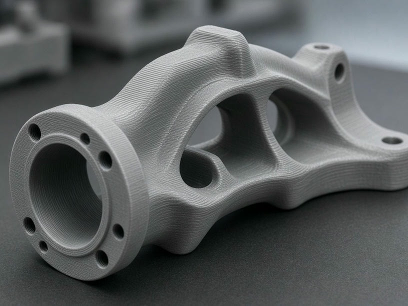
PartsMake provides industrial-grade additive manufacturing services that bridge the gap between rapid prototyping and functional end-use production. Use this guide to prepare CAD geometry that translates reliably from design intent to the shop floor.
5
Core processes
0.1–0.5
Clearance guidance
DFM
Engineering review
CAD
Ready to assess
Design parameters
Process-specific limits at a glance
These standard thresholds provide a practical starting point for high-quality parts. Final limits depend on geometry, material, build orientation, and the required finish.
| Feature | SLA | SLS | MJF | FDM | Metal DMLS/SLM |
|---|---|---|---|---|---|
| Minimum wall thickness | 0.5 mm | 0.8 mm | 0.7 mm | 1.2 mm | 1.0 mm |
| Minimum hole diameter | 0.3 mm | 0.5 mm | 0.5 mm | 1.0 mm | 0.5 mm |
| Minimum feature size | 0.2 mm | 0.5 mm | 0.5 mm | 0.8 mm | 0.4 mm |
| Self-supporting angle | 45° | 45° | 45° | 45° | 35° |
| Assembly clearance | 0.1 mm | 0.3 mm | 0.3 mm | 0.5 mm | 0.2 mm |
Values are standard manufacturing guidelines, not universal guarantees. Our engineering team validates critical features during DFM review.
Choose the right process
Technology-specific design considerations
Fine detail and cosmetics
Ideal for high-detail, cosmetic, and clear parts. Add drainage holes to hollow geometries to prevent resin entrapment.
Complex nylon geometry
No support structures are required, making SLS suitable for functional nylon parts, interlocking assemblies, and internal channels.
Production-grade output
Consistent mechanical properties and high throughput make MJF a strong fit for functional components and enclosures.
Large, economical prototypes
Useful for large prototypes, jigs, and fixtures. Account for anisotropic strength and reduced performance along the Z-axis.
Thermally managed parts
For DMLS and SLM, minimize large overhangs and provide heat dissipation paths to reduce warping during the build.
Design for the build
Orientation, clearances, and tolerance strategy
Additive manufacturing requires a different approach from machining. Build direction, thermal behavior, and layer formation all influence the finished component.
Minimize support contact on critical cosmetic surfaces.
Align the build direction with primary load-bearing axes to maximize structural integrity.
Reduce build time and material consumption to improve project economics.
Assembly guidance
Design for reliable fit
For mating parts, we recommend a general clearance of 0.2 mm to 0.5 mm depending on the selected technology. Standard machining tolerances do not automatically apply to printed parts.
High-precision fits
For press fits or bearing seats, design excess material for secondary CNC machining rather than relying solely on the printed surface.
Beyond the build
Post-processing for functional specifications
PartsMake manages the full lifecycle of your part, from initial print through secondary operations and final preparation for assembly.
Surface finishing
Bead blasting, sanding, and chemical smoothing for improved aesthetics.
Heat treatment
Stress relief or annealing for metal and high-performance plastic parts.
Threading
Helicoils or threaded inserts for robust mechanical fastening.
Protective coatings
Painting, powder coating, or anodizing for environmental protection and branding.
Engineering confidence
A DFM review before production
Before production, our engineering team checks wall thicknesses, draft angles, and critical tolerances against your project requirements. If a design flaw could compromise the build, we provide specific recommendations to optimize the geometry for the selected process.
Request a feasibility reviewStart your project
Partner with PartsMake
From a single prototype to repeat production of functional end-use parts, our team supports engineers and procurement teams from initial concept through delivery.
Ready to start? Upload your CAD files for a manufacturing feasibility review.
Email:
Facility:
Engineering inquiry