Precision Manufacturing Tolerance Guide
Optimize GD&T for cost and performance. At PartsMake, we treat tolerance as a primary driver of unit cost, inspection effort, and production lead time.
±0.002 mm
Precision grinding capability
GD&T
Function-led specification review
FAIR
Documentation available on request
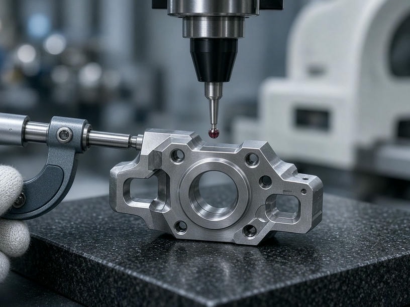
Tolerance is more than a number
Standard linear tolerances define acceptable feature-size variation. Geometric Dimensioning and Tolerancing provides the functional language needed to control complex assemblies and communicate design intent.
The right control describes how a part must function while avoiding unnecessary precision that adds cost and inspection time.
Flatness & parallelism
Essential for mating surfaces where poor control can cause leakage, uneven loading, or vibration.
Position & true position
Critical for bolt patterns, locating features, and shaft alignment in robotics and automation.
Concentricity & runout
Vital for high-speed rotating components used in semiconductor and automotive equipment.
Profile of a surface
Useful for complex 3D contours where traditional coordinate dimensions cannot fully define the geometry.
Typical achievable tolerances
Not every feature requires a tight tolerance. Use this comparison to align your design intent with realistic process capability before adding secondary operations or extended inspection cycles.
| Process | Typical standard tolerance | Precision / tight tolerance | Typical design consideration |
|---|---|---|---|
| CNC milling / turning | ±0.05 mm | ±0.01 mm | Strong balance of tolerance control and mechanical integrity |
| Precision grinding | ±0.01 mm | ±0.002 mm | Mating surfaces, high finish, and tight flatness |
| Wire EDM | ±0.01 mm | ±0.005 mm | Complex internal geometry and hardened materials |
| Sheet metal | ±0.20 mm | ±0.10 mm | Account for material behavior and formed-feature variation |
| Injection molding | ±0.10 mm | ±0.05 mm | Draft angles and shrinkage affect final tolerance |
| 3D printing | ±0.20 mm | ±0.10 mm | Geometry, orientation, and post-processing influence accuracy |
How tolerance affects production cost
Every increase in precision adds effort somewhere in the production and quality system. A function-first specification helps preserve performance without paying for unnecessary accuracy.
Machine time
Achieving ±0.01 mm can require slower feed rates, multiple roughing and finishing passes, and thermal stabilization of the equipment.
Tooling and setup
Tight position and profile tolerances often require custom fixtures or specialized work-holding to minimize part deflection.
Inspection overhead
As tolerances shrink, CMM verification takes longer. Micron-level measurements may require controlled environments and extended measurement cycles.
Mitigate tolerance risk before production
PartsMake performs a technical review of every CAD file and drawing before the machines start. If a tolerance is inconsistent with the material properties or selected process, we flag it immediately.
We also look for tolerance stacking: individual parts may meet their specifications while the assembled mechanism fails because minor deviations accumulate. Adjusting GD&T during the prototype phase helps prevent costly scrap during pilot and low-volume production.
Review focus
- ●Tolerance feasibility by material and process
- ●Potential tolerance stacking in assemblies
- ●Prototype-stage GD&T optimization
- ●Lead-time and scrap-risk reduction
Define inspection requirements early
Quality control is data-driven. Categorize features by criticality so inspection effort is focused where it protects assembly performance.
100% inspection
Use CMM or calibrated gauges for features that directly affect safety, fit, or core function.
Sampling plans
Use inspection sampling based on AQL standards for important but non-critical features.
Process checks
Verify through first-article inspection and periodic process checks.
If your project requires a First Article Inspection Report (FAIR) or Material Test Reports (MTRs), define these requirements in your RFQ.
Match the process to the geometry
Select a manufacturing method according to the part's primary functional requirement, not simply the smallest number on the drawing.
Mating surfaces
Precision grinding or hard turning can achieve high surface finish and tight flatness.
Complex internal geometry
Wire EDM is well suited to hardened materials and features milling tools cannot reach.
Structural components
CNC machining provides a strong balance of tolerance control and mechanical integrity for housings and brackets.
High-volume plastic parts
Injection molding requires careful consideration of draft angles and shrinkage, which directly affect final tolerance.
Tolerance planning FAQ
Validate your drawings before production
Send your CAD files and technical drawings to our engineering team for a feasibility assessment. We provide feedback on tolerance feasibility, material selection, and potential design optimizations to reduce lead times.
Submit your files for a formal quote
Include your drawings, target quantities, materials, and inspection documentation requirements.