Injection Molding Design for Manufacturing
Custom Injection Molding: Design for Manufacturing Guide
PartsMake helps engineering teams move from CAD validation to reliable, scalable injection molding production. Get practical guidance on wall thickness, draft, ribs, bosses, gates, ejectors, and common molding risks.
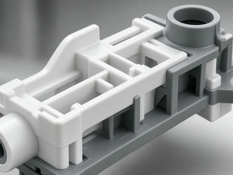
50–50,000+
Prototype to production volumes
DFM First
Risks identified before tooling
01
Design confidence
Resolve geometry risks before mold steel is cut.
02
Production continuity
Coordinate prototypes, tooling, inspection, and repeat production.
03
Engineering communication
Work directly with specialists who understand tolerances and materials.
Core geometry principles
Build a part that fills, cools, and ejects cleanly
Successful plastic parts rely on consistent geometry. The following design choices reduce cosmetic defects, structural failure, cycle time, and avoidable tooling complexity.
Wall thickness
Maintain uniform walls to prevent sink marks and warpage. Avoid abrupt thickness changes and use gradual transitions where sections must vary.
Draft angles
Use at least 0.5°–2° on vertical walls, with more draft for deep features or textured surfaces, so parts release without scuffing.
Ribs and bosses
Keep ribs near 50%–60% of nominal wall thickness and boss walls near 40%–60% to add strength without creating visible sink or ghosting.
Release strategy
Minimize undercuts that require side-actions or lifters. Place ejector pins on hidden or non-cosmetic surfaces and plan for balanced release.
Corner radii
Use internal radii of approximately 0.25–0.5 times the nominal wall thickness. Rounded transitions improve material flow and reduce stress concentration.
Gate placement
Strategic gates control flow, packing, weld lines, and cosmetic outcomes. Gate locations should be reviewed against filling and functional requirements.
Venting and ejection
Provide venting where air may become trapped, and plan ejector-pin locations early to support automated part removal without marking visible faces.
Engineering reference
Material-based design parameters
Use these starting ranges during concept development. Final values depend on resin grade, fiber content, texture, geometry, tooling, and the required finish.
| Material family | Typical wall thickness | Draft angle | Rib thickness | Boss wall | Shrinkage allowance |
|---|---|---|---|---|---|
| ABS | 1.5–3.0 mm | 0.5°–1.5° | 0.5–0.6 × wall | 0.4–0.6 × wall | 0.4%–0.8% |
| Polypropylene (PP) | 1.0–3.0 mm | 0.5°–1.5° | 0.5–0.6 × wall | 0.4–0.6 × wall | 1.0%–2.0% |
| Polycarbonate (PC) | 1.5–3.5 mm | 1°–2° | 0.5–0.6 × wall | 0.4–0.6 × wall | 0.5%–0.8% |
| Nylon (PA) | 1.5–3.5 mm | 1°–2° | 0.5–0.6 × wall | 0.4–0.6 × wall | 0.8%–2.0% |
| General reference | 1.5–3.0 mm | 1° per 25 mm depth minimum | 0.5–0.6 × wall | 0.4–0.6 × wall | 0.3%–2.0% |
Troubleshooting matrix
Connect visible defects to design causes
A defect may have multiple process causes. These design-focused checks provide a practical starting point for DFM discussion.
| Defect | Primary design cause | Design-focused corrective action |
|---|---|---|
| Sink marks | Thick sections or ribs | Reduce wall and rib thickness, add radii, or core out mass |
| Warpage | Non-uniform cooling or unbalanced geometry | Balance wall thickness and review gate and cooling strategy |
| Short shot | Flow restriction or insufficient section thickness | Improve flow paths, increase local thickness where justified, or review gate size |
| Flash | Parting-line or shutoff risk combined with pressure | Improve mold fit and shutoff design; review clamping and parting surfaces |
| Burn marks | Trapped air in the filling path | Add venting and reconsider gate or flow-front placement |
| Ejector marks | Insufficient release draft or concentrated ejection force | Increase draft, add suitable ejector support, and move pins to hidden surfaces |
From prototype to production
One coordinated manufacturing path
PartsMake coordinates multiple production processes to deliver ready-to-assemble components while maintaining design consistency through every stage.
Prototype
Rapidly verify form, fit, interfaces, and key ergonomic assumptions.
Engineering samples
Test material properties, assembly logic, and critical design functions.
Pilot production
Validate tooling stability, process capability, and inspection requirements.
Repeat production
Deliver consistent, quality-controlled output for your supply chain.
Integrated capabilities
CNC machining
3-, 4-, and 5-axis milling for mold bases, inserts, and precision metal components.
Sheet metal
Enclosures, brackets, and panels that complement plastic assemblies.
Surface finishing
Bead blasting, anodizing, painting, and texture application for functional or cosmetic needs.
Quality inspection
CAD-based dimensional verification using CMM and calibrated manual inspection tools.
Why engineering teams choose us
Technical assessment before rapid quoting
Every RFQ receives an engineering review designed to identify manufacturing risks before tooling begins.
Risk mitigation
Flag DFM issues such as draft angles, wall thickness, undercuts, and ejection before metal is cut.
Process coordination
Manage secondary processes, assembly, and packaging through a single point of contact.
Scalable production
Support volumes from 50 engineering samples to 50,000 production units and beyond.
Technical communication
Communicate directly with specialists familiar with tolerances, material science, and inspection protocols.
Industry applications
Built for high-reliability sectors
Robotics & automation
Complex housings and structural components.
Medical & laboratory
Precision parts requiring strict material compliance.
EV & new energy
Thermal management components and high-tolerance enclosures.
Aerospace & drones
Lightweight, high-strength parts produced to tight specifications.
FAQ
Practical questions before tooling
What files should I submit for a DFM review? +
Provide 3D CAD files in STEP or IGES format, plus a 2D drawing showing critical dimensions, material specifications, tolerances, and surface finishes.
How early should draft and gate locations be reviewed? +
Review them before tooling design is finalized. Early decisions help prevent ejection problems, visible weld lines, cosmetic defects, and expensive mold changes.
Can one supplier manage related processes? +
Yes. PartsMake coordinates injection molding with CNC machining, sheet metal fabrication, finishing, inspection, assembly, and packaging.
Submit your project
Get a quote and actionable DFM feedback
Send your 3D CAD files and 2D drawings for an engineering-led review of materials, geometry, tooling, finish, and production requirements.
Preferred formats: STEP or IGES, plus 2D drawings
Email:
Office: