Custom Insert Molding Services for Complex Plastic-Metal Assemblies
PartsMake integrates brass inserts, threaded sleeves, terminals, shafts, and metal skeletons directly into engineered plastic parts during injection molding.
Reduce secondary assembly, improve structural integrity, and create reliable threaded, conductive, or load-bearing connection points in a single production process.
50–800T
Injection molding range
±0.03 mm
Tightest stated tolerance
1M+
Typical maximum units
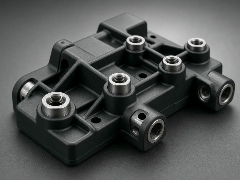
Built for demanding interfaces
A controlled combination of insert preparation, mold positioning, resin selection, and process stability supports repeatable performance.
Engineering integration
How insert molding creates a permanent bond
Pre-manufactured metal components are placed into the mold cavity before resin injection. As the plastic cools, it encapsulates the insert and forms a cohesive plastic-metal assembly.
Prepare
Define insert geometry, resin, tolerances, and functional loads.
Position
Secure each insert with engineered locators or vacuum-assisted positioning.
Encapsulate
Inject and cool the polymer to produce a stable, integrated part.
Technical specifications
A production platform for intricate and structural parts
Our 50–800 ton injection molding machines support small electronic components through larger structural assemblies, with production volumes from development quantities to high-volume programs.
| Feature | Specification |
|---|---|
| Insert materials | Brass, stainless steel, copper, aluminum, steel |
| Insert types | Threaded inserts, terminals, pins, shafts, metal skeletons |
| Plastic materials | ABS, PC, Nylon (PA), PEEK, PPS, TPU, TPE |
| Recommended wall thickness | 0.5 mm–3.0 mm |
| Tolerance | ±0.03 mm to ±0.20 mm |
| Production volume | 100 to 1,000,000+ units |
| Mold steel | P20, 718H, NAK80, S136, H13 |
Engineering for structural reliability
Insert molding performance depends on controlling torque, pull-out loads, thermal behavior, and stress around the metal-plastic interface.
-
●
Insert anti-rotation design
Knurling, hexagonal profiles, and undercuts create mechanical interlocks that resist spinning during torque application.
-
●
Pull-out strength
Encapsulation depth and plastic shrinkage rates are considered to maximize the mechanical bond between insert and polymer.
-
●
Crack prevention
Uniform wall thickness and appropriate thermal expansion properties help reduce stress concentrations around the insert.
Precision positioning and throughput
The insert must remain stable while high-pressure resin flows through the cavity. Custom-engineered locator pins and vacuum-assisted positioning help maintain alignment before and during injection.
Automated loading
Automated systems place inserts consistently, reduce cycle time, and lower manual loading costs.
Tooling strategy
Bridge molds and high-cavity production tools are evaluated for the required launch volume and throughput.
Material compatibility
Match the resin to the metal interface and end use
We work with standard thermoplastics and high-performance engineering plastics for thermal, structural, conductive, and soft-touch requirements.
High temperature
PEEK & PPS
For automotive or aerospace applications where thermal stability is essential.
Reinforced
Glass-filled Nylon
Adds structural rigidity and wear resistance to demanding assemblies.
Flexible
TPU & TPE
Supports overmolding and soft-touch interface applications.
From DFM to final assembly
A practical path from CAD review to production-ready components
DFM review
Review CAD models, draft angles, rib placement, and gate locations for insert molding.
Tooling design
Develop locator features and mold layouts around insert stability and production volume.
Molding
Run controlled injection processes for repeatable placement and encapsulation.
Finishing
Add laser marking, printing, or full-scale sub-assembly for line-ready delivery.
Common project questions
Plan the metal-plastic interface with confidence
What insert types can be integrated? +
Supported insert types include brass and threaded inserts, sleeves, terminals, pins, shafts, and metal skeletons, subject to part geometry and tooling review.
How are inserts kept from moving during injection? +
Custom locator pins and vacuum-assisted positioning stabilize the components and help prevent displacement caused by high-pressure resin flow.
What files are needed for an initial review? +
Send 3D CAD files in STEP or IGS format together with technical requirements, expected volume, and any pull-out, torque, electrical, or thermal targets.
Can you provide secondary assembly services? +
Yes. Secondary finishing can include laser marking, printing, and full-scale sub-assembly to deliver finished components ready for your production line.
Request a project review
Start with your CAD files and technical requirements
Share your STEP or IGS files and project details. PartsMake will conduct a DFM analysis and provide a lead-time estimate for your mold and production run.